
One of my FIPs was broken down recently after serving my flightsimming system stably for more than a decade. I opened its case to see if it is self-serviceable. Unfortunately all electronics components, except the LCD screen, were surface-mounted onto the circuit board.
Followings are the teardown pictures of the unit for those who are interested to see what are packed inside the FIP.
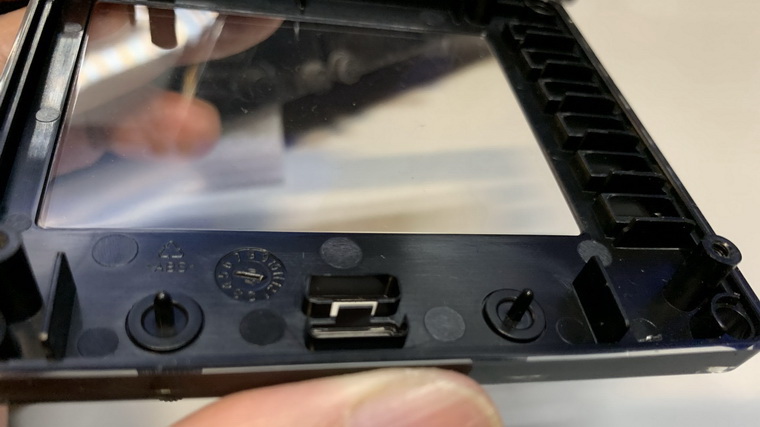
Opening the case isn’t difficult at all. Just unscrew the 4 screws on the backside of the panel. That will do.
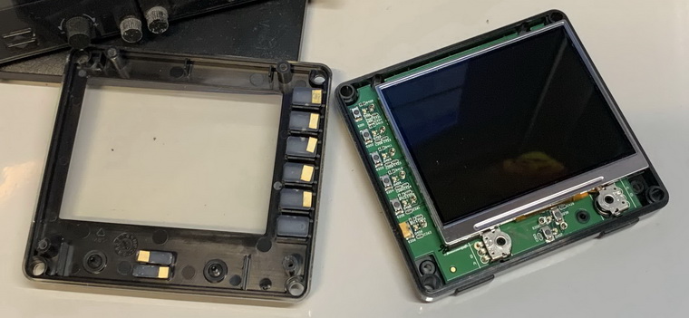
Since major electronics components were all surface-mounted onto the circuit board, the interior looks clean and tidy. But to tear off the LCD screen, it took some efforts as it was sticked onto the circuit board firmly.
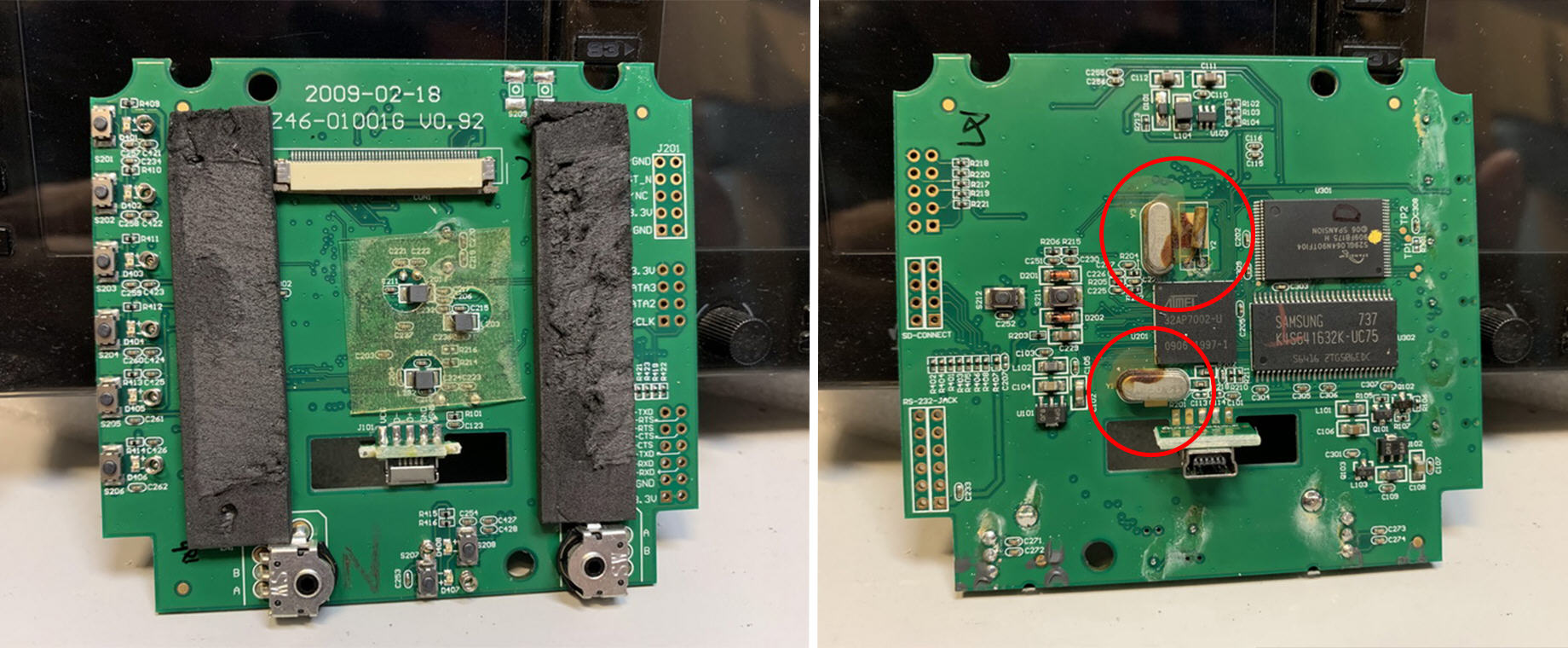
Light switch controls and the LCD connector are placed on one side, and the controller processors on the other. The 3 components circled in the left image below were burned a little, which are very likely the cause of death of the unit.
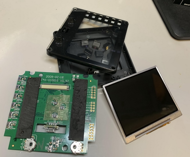
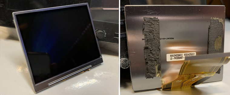
The LCD screen is intact and therefore kept in a safe place, just in case be used as a replacement if the screen of any of my other FIPs got worn out.
The face-plate is also a valueable asset to keep since the two knobs on it are simply unrepairable if they are broken, which is not uncommon on aged FIPs. (Edit: Oz Flyer suggested two solutions of reparing the buttons in the Comment section below. Sounds good!)
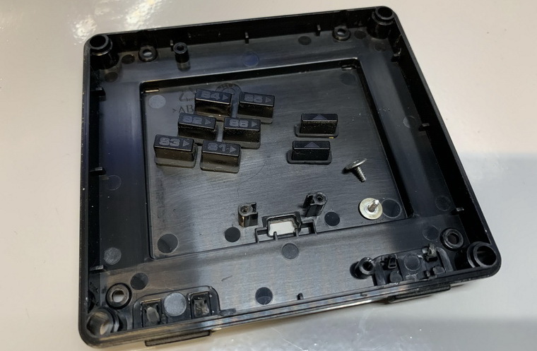
The remaining back-plate and screws and buttons are more likely to be trashed as the possibility of reusing them in the future is slim.
Although I feel a bit sad to see the unit died, the recycling of some parts from the remains of it still brings some comforts any way.

You commented that the knobs are not repairable, that not quite right as I have repaired 2 so far after a 7″ LCD fell over on them. I have also told other how to fix theres.
They seem to brake where the shaft is glued to the inside back of the knob.
After pulling the unit apart the shaft can be removed from the inside.
1) Cover most of the shaft with silicon grease leaving just the end that stick out the front of the case clean.
Then using a pin or some other small device place supper glue on the very end and put the knob back on.
2) A friend told me that he 3D printed a new knob and use a 2mm RC model control rod as the shaft.
LikeLike
Sounds good, David. I tried before without applying silicon grease you suggested.
I’ll give it a try again with the gluing method you suggested.
Thanks very much.
P.S. I mentioned your suggestions in the article as well.
LikeLike
Hi Tom,
If those are the faulty components they are cheap and easy to replace, the skinny bits are likely to be capacitors and the oval shaped ones are timing crystals. It could restore the unit which looks like it’s had liquid inside.
Joe.
LikeLike
Two other guys said that those brown marks might be glues turned old instead of burns. Probably right as they don’t have burnt smell.
I described the symptoms when the unit was dying to another comments earlier. You might have a look.
The LCD panel is fine since I tried it on another good FIP and it works normally.
Will keep the parts for awhile and check out if anyone out there could help on it before I really dump it.
Thanks
LikeLike
Hi Tom,
As far as I can see on the picturesthe 3 components ar Quarz units that are glued to the board , a common practice to avoid vibration. It looks that due to the age, the glue became brown.
If the display stayed dark, it could have been a backlite problem.
Best regards,
Roger
LikeLike
You’re probably right that they are not burn marks but glues turned old. I suspected it before but since other components look normal so they are the ones to blame…haha.
Problem from backlite ? Do you mean the backlite on the LCD panel ?
I put the LCD panel onto another FIP and it works fine. So probably something else has gone wrong.
Thanks
LikeLike
Most likely some component on the board stopped delivering proper power level to the backlight and other components. This can be easily diagnosed and fixed by a professional.
LikeLike
You are right but unfortunately I don’t know any professional friend of this kind. The cost of getting professional on the street may be well beyond the price of a new FIP. haha
Will see what I can get.
LikeLike
Those are not burn marks, that’s some sort of glue to keep the quartz oscillators on board. I suspect your unit had power issues or backlight failure. The first ones are easily fixable, however, the backlight may require a new screen. The screen would be probably hard to find. In any case I would not scrap a unit until you know what the problem was.
LikeLike
You are the second person saying those marks are glues turned old instead of burning…haha. You guys are probably right.
When the problem started, the FIP worked OK for a few minutes and then the LCD flashed a bit and then turned black.
It reacted similarly for a few days whenever the USB was disabled and enabled.
The unit was plugged onto a powered USB hub. I tried plugging the FIP onto other ports and it reacted the same.
By the time I tore it apart, the red LEDs for buttons flashed less than a second then everything stopped when I enabled the USB. Nothing shows on the screen.
Later, the LEDs didn’t flash at all.
Yes, will keep the unit for awhile in case there’s a chance of fixing it.
Thanks
LikeLike